solar inverter diagram
Understanding Solar Inverter Diagrams A Comprehensive Guide
As the world increasingly turns toward renewable energy, solar power has emerged as a leading solution for sustainable electricity generation. At the heart of any solar power system is the solar inverter, a critical component that transforms direct current (DC) generated by solar panels into alternating current (AC) that can be used by home appliances or fed into the electrical grid. Understanding the solar inverter and its diagram is essential for anyone looking to delve deeper into solar technology.
What is a Solar Inverter?
A solar inverter is an electrical device that converts the DC electricity produced by solar panels into AC electricity, which is the standard form of electricity used in most household appliances and the electrical grid. Solar inverters also perform multiple functions, such as monitoring the performance of solar panels, ensuring safety through rapid shutdown capabilities, and maximizing energy output via techniques like maximum power point tracking (MPPT).
Key Components of Solar Inverter Diagrams
A solar inverter diagram typically includes several essential components and functionalities. Below are the main elements often represented in such diagrams
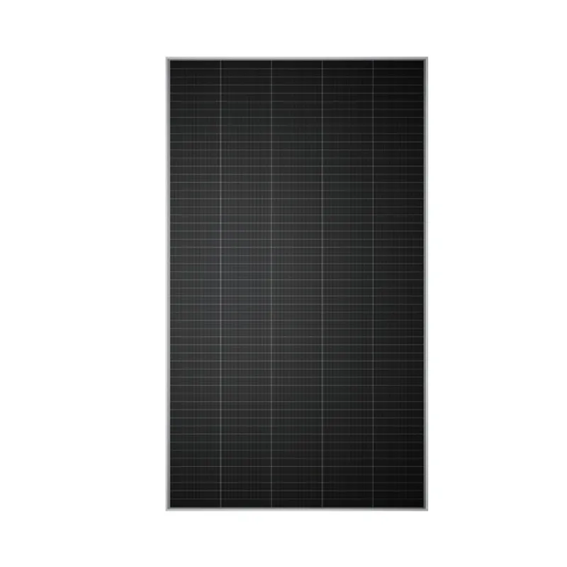
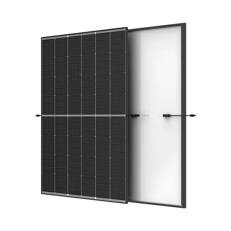
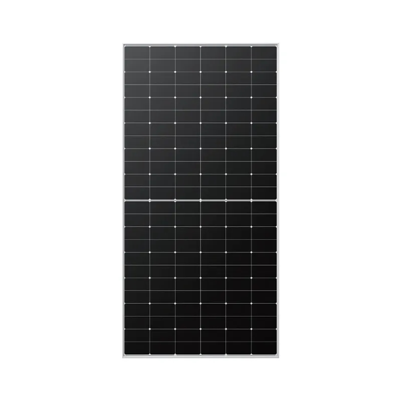
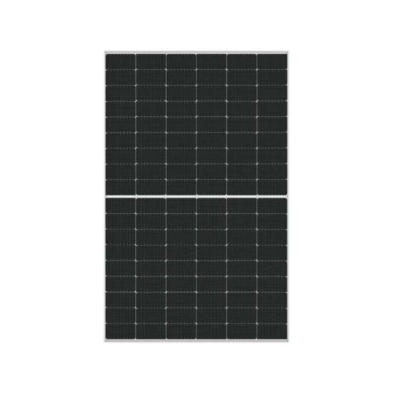
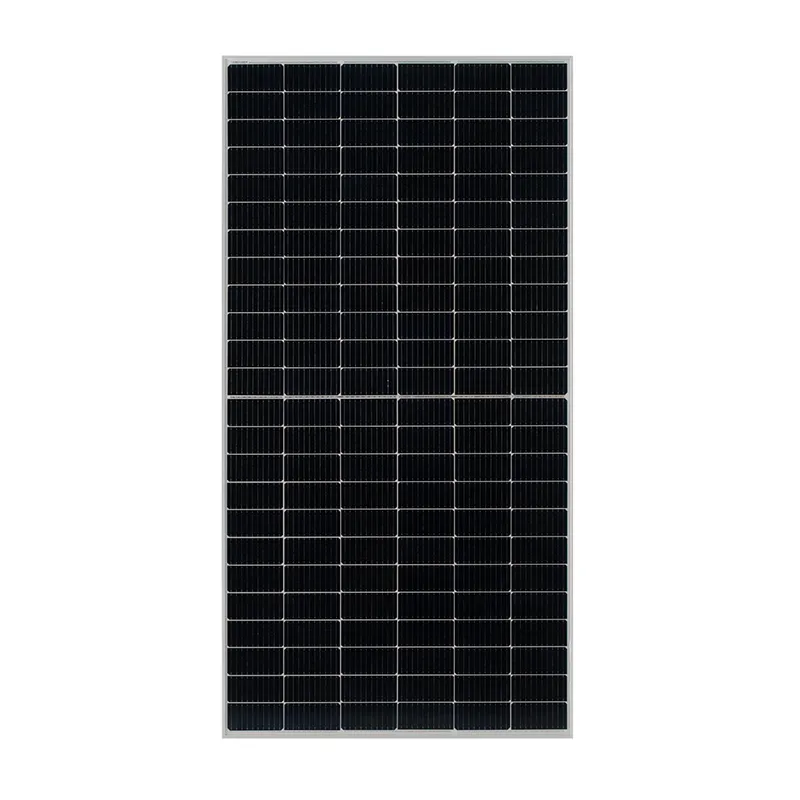
1. Solar Panels The starting point of the solar power system, solar panels capture sunlight and convert it into DC electricity. In a diagram, these are usually represented as large rectangles or squares with symbols indicating photovoltaic cells.
2. Inverter Input This portion of the diagram shows how the DC electricity from the solar panels is directed into the inverter. It often includes fuses or breakers for safety, ensuring that electricity flows safely into the inverter.
3. Inverter The inverter itself is represented prominently. Within the inverter, various internal components are illustrated, such as transformers, capacitors, and control circuits. These elements work together to convert DC to AC power.
solar inverter diagram
4. AC Output After conversion, the AC electricity is represented as flowing out of the inverter. This output may lead directly into a home's electrical system or connect to the grid, depending on the specific setup.
5. Monitoring and Control Systems Many modern solar inverters come equipped with monitoring systems. Diagrams may illustrate communication links with monitoring devices or mobile apps, enabling users to track their system's performance in real-time.
6. Safety Features Many diagrams will include safety features like circuit breakers or emergency shutdown switches, ensuring the system can be safely turned off or disrupted during maintenance or emergencies.
How to Read a Solar Inverter Diagram
To effectively read a solar inverter diagram, one needs to understand the flow of electricity from source to output. Start by identifying the solar panels at the left side of the diagram. Trace the connection to the inverter, taking note of any safety components like fuses or disconnect switches. Next, observe how the inverter transforms the electricity, and finally, follow the output lines leading to either home appliances or utility connections.
Understanding symbols is also important in reading these diagrams. Different shapes and lines represent various components, with dashed lines often indicating communication paths and solid lines denoting electrical connections.
Conclusion
Solar inverter diagrams serve as crucial tools for understanding how solar power systems operate. By visualizing components like solar panels, the inverter itself, and the flow of electricity, one gains insight into how solar energy is processed and utilized. Whether you are a homeowner considering solar energy installation, an engineer working on solar technology, or simply a renewable energy enthusiast, familiarity with solar inverter diagrams will enhance your knowledge and appreciation of solar energy systems. As solar technology continues to evolve, these diagrams will remain a foundational aspect of understanding how we harness the power of the sun.
-
String Solar Inverter: The High-Efficiency Solution for Smart Solar EnergyNewsJul.14,2025
-
Revolutionizing Rooftop Energy with the Power of the Micro Solar InverterNewsJul.14,2025
-
Power Independence with Smart Off Grid Solar Inverter SolutionsNewsJul.14,2025
-
On Grid Solar Inverter: Powering the Future with Smart Grid IntegrationNewsJul.14,2025
-
Monocrystalline Solar Panels: High-Efficiency Power for the Future of Clean EnergyNewsJul.14,2025
-
Bifacial Solar Panel: A Smarter Investment for Next-Generation Energy SystemsNewsJul.14,2025
